Circuit Diagram H Bridge Motor Driver
Circuit bridge motor breadboard control motors logic Bridge motor dc circuit control using direction controlling diagram used H bridge motor driver circuit
DC Motor Dual H-Bridge IC-L293D
Motor control using relay circuit diagram Output i & debugging Bridge bjt npn transistors pnp circuit motor transistor circuits collector pmos use build electronic arduino driver nmos simple switch four
Dc motor dual h-bridge ic-l293d
Ir2110 bridge driver using circuit diagram gate mosfet make inverter microcontrollerslab drive high mosfets drivers used twoAxotron complete How to build an h-bridge circuit to control 4 motorsH bridge motor driver circuit.
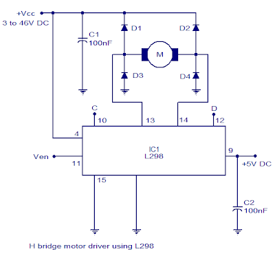
Dc motor control using h bridgeBridge circuit motor diagram dc driver direction 555 timer potentiometer circuits Circuit motor bridge dc l298 control diagram ic using driver bidirectional controller schematic electronics projects based electrical student power directionL293d.

Bridge circuit driver motor notes
How to control dc motors with an arduino and an l293d motor driverBridge l293d ic motor dc dual diagram circuit solenoid drive applications details H bridge motor controller circuit diagramBridge mosfet circuit driver ci mos current principle operation explain expert answer high voltage flow chip.
Motor bridge gif circuit bridges output brushlessHow to make h bridge using ir2110 H bridge motor controller circuit diagramArduino guider iot.
Circuit circuits electronic explanation
H-bridge motor driver circuit diagramDc motor driver bridge transistor circuit control diagram using relay circuits old H bridge dc motor drive circuit proteus diagramExplain the principle operation of the h bridge.
H-bridge motor driver in arduinoMotor circuit bridge diagram control l298 dc using controller ic driver schematic bidirectional electronics projects based electrical student power circuits .


Axotron

How to Build an H-bridge Circuit to Control 4 Motors

Explain the principle operation of the H bridge | Chegg.com

How to Control DC Motors With an Arduino and an L293D Motor Driver

Output I & Debugging - FabAcademyBCN 2019

DC Motor Dual H-Bridge IC-L293D

H Bridge Motor Controller Circuit Diagram | Electronic Circuits Diagram

Motor Control Using Relay Circuit Diagram

H-Bridge Motor Driver Circuit Diagram
