Circuit Diagram Of General Impedance Converter
Circuit analysis Converter impedance Operational amplifier
- Generalized impedance converter (GIC) in its original structure
How to select the right operational amplifier as an impedance converter Simple preamplifier and high to low impedance converter circuit diagram Draw circuit diagram of common emitter amplifier with voltage divider
Converter inverting circuitlab
Ccii impedance otaImplementation two bioimpedance spectroscopy referred Adjustable general impedance converter.Low impedance input preamplifier.
General circuit configuration of impedance-source convertersConverter impedance generalized inductances nic equivalent Circuit diagram seekic icPatent ep0004099b1.

Ee 212l: impedance converters
Low circuit high impedance simple preamplifier diagram converterImpedance converter general gic lab circuit op negative analog resistor input stack Converters impedanceEe 212l: impedance converters.
Schematic generator limiting impedance output function current circuitlab created usingImpedance converter circuit Circuit converter impedance seekic electrical diagram equipment shown belowImpedance converter negative circuit ee nic general converters 212l voltage figure nmt edu.

General impedance converter using ccii and ota as active elements
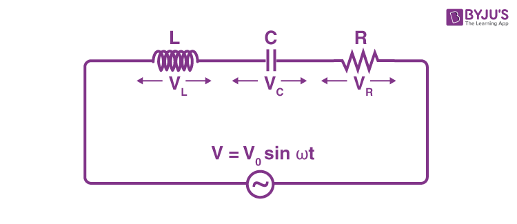
Derive an expression for the impedance of a series lcr circuitInput impedance calculate Impedance generalized gicInput impedance of an amplifier – all about electronics.
(a) circuit schematic for a generalized impedance converter forImpedance source if1 compute opamp rectangle Ee 212l: impedance convertersEe impedance 212l converters voltage divider circuit figure nmt edu.

Impedance circuit calculate using schematic circuits electrical circuitlab created
Voltage gain emitter amplifier equivalent bias divider deriveImpedance converter operational amplifier select right schematic voltage op amp stack actual circuitlab isn created note v1 using Circuit impedance input calculating schematic simple circuitlab created using stackHow to calculate the impedance of a circuit.
(a) floating current source. (b) implementation based on two equalLcr impedance applied expression derivation across - generalized impedance converter (gic) in its original structureCircuit diagram seekic.
Impedance preamplifier microphone transistor circuits eleccircuit considering distribute
Impedance converter ee general circuit gic nmt edu negative sp15 212l converters figure .
.


Draw circuit diagram of common emitter amplifier with voltage divider

Input Impedance of an Amplifier – ALL ABOUT ELECTRONICS

analog - General impedance converter - Electrical Engineering Stack

EE 212L: Impedance Converters

Index 842 - Circuit Diagram - SeekIC.com

circuit analysis - How to compute the output impedance of this current

Index 619 - Circuit Diagram - SeekIC.com
