Excess 3 Adder Circuit Diagram
Adder cmos circuit diagram fa transistor using 28t transistors implementation edacafe transmission gate power fig www10 phdthesis book Full adder circuit diagram Bcd to excess 3 code convertor in cs1206 digital lab
EDACafe: Power, accuracy and noise aspects in CMOS mixed-signal
3 bit full adder : 3 bit full adder Solved 4. (a) construct a 4-bit binary adderisubtractor Adder binary carry watson latech sum inputs circuits along
Adder cascaded
Edacafe: power, accuracy and noise aspects in cmos mixed-signalThe two half adder circuits cascaded together forms a full adder Adder excess binary construct bcd converterAdder circuit diagram schematic works figure.
Bcd excess diagram logic code converterAdder logic half implementation Full-adder circuit, the schematic diagram and how it works – deeptronicAdder circuit.

Full adder – electronics post
Bcd code excess convertor lab digital clickExcess-3 to bcd logic diagram – zzoomit .
.


Excess-3 to BCD logic diagram – Zzoomit
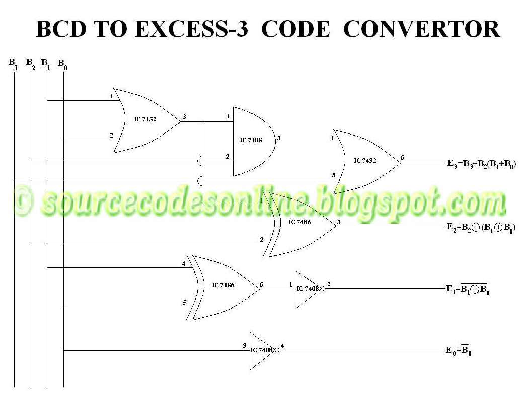
BCD to Excess 3 Code Convertor in CS1206 Digital Lab - Source Code

The two half adder circuits cascaded together forms a full adder

Full-Adder Circuit, The Schematic Diagram and How It Works – Deeptronic

EDACafe: Power, accuracy and noise aspects in CMOS mixed-signal

3 Bit Full Adder : 3 bit Full Adder - YouSpice / While full adder adds

Full Adder Circuit Diagram | Download Scientific Diagram

Full Adder – Electronics Post
